Difference between revisions of "Guide to circuits"
imported>DrWoofington |
imported>DrWoofington |
||
| Line 6: | Line 6: | ||
Each machine can hold a limited amount of components, limited by both number of components, as well as an abstract 'complexity' value for each component. Complex components are generally things that interact with the outside world, like weapon systems, or a fast pulse ticker. Smaller machines will have stricter limits on how many things can be shoved inside at once, where as larger ones allow for more space, but are less space efficient when carrying it. | Each machine can hold a limited amount of components, limited by both number of components, as well as an abstract 'complexity' value for each component. Complex components are generally things that interact with the outside world, like weapon systems, or a fast pulse ticker. Smaller machines will have stricter limits on how many things can be shoved inside at once, where as larger ones allow for more space, but are less space efficient when carrying it. | ||
| + | ==Tools== | ||
| + | The primary method for interacting with devices is through specialized tools. | ||
| + | *[[File:Circuitprinter.gif]]Integrated Circuit Printer: Makes all the bits for your cool new toys as well as all the tools ( the wiring tool, debug tool and circuit analyzer ) | ||
| + | *[[File:circuitwirer.gif]]Circuit Wirer: allows you to wire and unwire inputs and outputs. Outputs should only be wired to Inputs of a compatible type! | ||
| + | *[[File:circuitdebugger.gif]]Circuit Debugger: Allows you write Refs, Strings, numbers or the null value to any buffer and send pulses. | ||
| + | *[[File:circuitanalyzer.gif]]Circuit Analyzer: Allows you to get a text string used to copy devices. | ||
| + | *Multitool: Writes to bools and pulses. | ||
| + | *Crowbar: Lets you open the device shells to modify them | ||
==Pins== | ==Pins== | ||
[[File:Pins.png]] | [[File:Pins.png]] | ||
| Line 21: | Line 29: | ||
==Wiring== | ==Wiring== | ||
| − | To wire something, you first need a special 'wiring' tool. You will also need a custom machine item, which resembles a cube, and some special circuits. All of this can be printed in R&D, and in the future can be found in tech storage. | + | [[File:circuitwirer.gif]]To wire something, you first need a special 'wiring' tool. You will also need a custom machine item, which resembles a cube, and some special circuits. All of this can be printed in R&D, and in the future can be found in tech storage. |
Other tools you may need are screwdrivers, which will remove circuits from the machine, and crowbars, to open or close machines. | Other tools you may need are screwdrivers, which will remove circuits from the machine, and crowbars, to open or close machines. | ||
| Line 45: | Line 53: | ||
null | null | ||
| − | |||
| − | |||
| − | |||
| − | |||
| − | |||
| − | |||
| − | |||
| − | |||
==Terms== | ==Terms== | ||
Revision as of 17:40, 17 November 2017
Research is now capable of building custom machines, using integrated circuits, that will hopefully accomplish whatever goal the creator had set out for the machine to solve, such as a health monitoring system, smart turret, a signaler controller for their bombs, or perhaps something to give Beepsky a run for their money. Or perhaps something else entirely, as more and more new parts get added to expand the metaphorical toolbox for these creators.
The Machine and Components
Each machine can hold a limited amount of components, limited by both number of components, as well as an abstract 'complexity' value for each component. Complex components are generally things that interact with the outside world, like weapon systems, or a fast pulse ticker. Smaller machines will have stricter limits on how many things can be shoved inside at once, where as larger ones allow for more space, but are less space efficient when carrying it.
Tools
The primary method for interacting with devices is through specialized tools.
 Integrated Circuit Printer: Makes all the bits for your cool new toys as well as all the tools ( the wiring tool, debug tool and circuit analyzer )
 Circuit Wirer: allows you to wire and unwire inputs and outputs. Outputs should only be wired to Inputs of a compatible type!
 Circuit Debugger: Allows you write Refs, Strings, numbers or the null value to any buffer and send pulses.
 Circuit Analyzer: Allows you to get a text string used to copy devices.
- Multitool: Writes to bools and pulses.
- Crowbar: Lets you open the device shells to modify them
Pins
A component, generally referred to as a circuit, has 'pins' on it, of three different types. Pins are connected to other pins, on the same circuit or on another circuit inside the machine, and are used to pass information or activation pulses from one component to another.
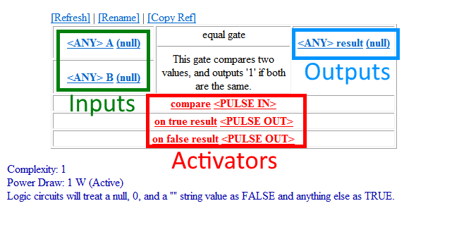
Most components have three types of pins, but some components may have only one or two types. The three types are input, output, and activation.
Input pins, as named, are what the circuit uses as input, where as the output pins are where the results go. For example, an addition circuit will sum up all the numbers it finds in their input pins, then put the result in their output pin. Activation pins are special, in that they don't carry data, but instead act as triggers for a component to do work. The addition circuit needs to receive a pulse signal to its activation pin in order for it to actually compute the sum of the inputs. When a circuit does work, and places its output in the outpin pins, it will then 'push' the data to any pins linked to the output pins, so that those pins will have the correct data. Most circuits do not 'pull' data, but instead need to have it 'pushed' from another circuit.
A pin can be linked to an arbitrary number of other pins, as long as they are inside the same machine. Removing a component will automatically unwire everything from it, so keep that in mind.
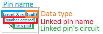
On the wiring interface, input pins are always on the left, output pins are on the right, and activator pins are on the bottom side. They are also colored red. Pins that are linked to to other pins are bolded, and will have a link to go to that circuit underneath. The data that pin holds, and the type it is, will also be visible.

Wiring
![]() To wire something, you first need a special 'wiring' tool. You will also need a custom machine item, which resembles a cube, and some special circuits. All of this can be printed in R&D, and in the future can be found in tech storage.
To wire something, you first need a special 'wiring' tool. You will also need a custom machine item, which resembles a cube, and some special circuits. All of this can be printed in R&D, and in the future can be found in tech storage.
Other tools you may need are screwdrivers, which will remove circuits from the machine, and crowbars, to open or close machines.
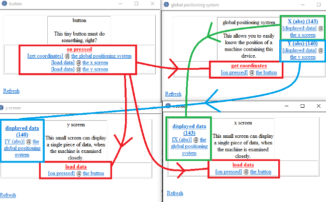
First, use a crowbar on the machine to open it, if it is not opened already, then start sliding some circuits inside. You'll hear it slide into place if there's enough room and it's not too complex. After that, examine or hit the cube with the wiring tool, then select a circuit to look at. After that, click on a pin, then on another pin, on the same or a different circuit, and they'll link together. Remember that activation pins don't carry data, and so can't be linked to input/output pins.
To unwire, just use the wire tool in your hand to change it to unwire mode, then click two pins to unwire them. Data
Pins can hold three types of data, which are strings (text), numbers (both integers and floating-point, because BYOND), and object references (called Refs). If there is no data in a pin, it displays 'null'.
Some circuits mandate that input data be a specific type of data. For example, a circuit wanting X and Y coordinates will require that those inputs be numbers. If it's given text, it will do nothing, and therefore won't work. Sometimes numbers can be converted to text, and text to numbers, with specialized circuits. For example, the number 5 can become the string “5”.
On the wiring interface, you can tell what type a piece of data is by looking at how it is presented, between two brackets. Strings are always wrapped in quotes, as in many programming languages, where are numbers are not, and are (obviously) only numbers. References have a [Ref] at the end of the name for the referenced object, and no quotes. Refs are somewhat more rarely used, but are powerful.
Numbers can be converted to strings easily with a number to text circuit. String can become numbers with a text to number circuit, so long as the string has only numbers inside of it (e.g. “28”. “Five” won't work). Refs can be converted one way to text, which will give you the name of the referenced object, using a ref to text circuit.
Valid types for pin data;
   “This is a string.”
   98.5
   the crowbar [Ref]
   null
Terms
Circuits work with two kinds of signals.
- Pulses: used to coordinate the device and tell circuits to act.
- Data: a value that the circuits store act, with, modify, and transmit as outputs.
- Strings are plain text values.
- Numbers are a numerical value that can have math done on it.
- Booleans are a special Number expecting any number >=1(True) or 0(False)
- Refs are references to specific objects in the world.
Flow Control
Flow Control is a term used generally for programming languages for determining in what order does code get executed. The same principal applies for custom machines, using activator pins. The proper management of how a pulse goes to each component in the correct order will be very important for complicated or big machines.
Fortunately, there are some components to help with organizing your flow control. For example, there are pulse splitters to allow for cleaner wiring. Delay timers also exist so that you can make sure everything goes off at the right time (although it's best if your machine is not dependent on that, which is known as a race condition in programming). Many circuits will also propagate a pulse if it passes a certain condition, for example many logic gates, ensuring that something will occur only if you want it to.


